Antenna selection including how to take advantage of low-cost solutions from Cypress for use in Bluetooth Low Energy BLE applications. Microstrip Design And External Antenna The MBN52832 module is certified with an internal PCB antenna and two external antennas. Antenna design and rf layout guidelines.
Antenna Design And Rf Layout Guidelines, The antenna trace width is 20 mils throughout. Antenna design including antenna parameters types and guidelines for placement enclosures and ground planes. Document information Info Content Keywords PN7120 NFC Antenna Design Antenna matchingtuning. A 7 dBi omni antenna and a 6 dBi patch antenna.
 How To Design A Pcb Antenna For 2 4ghz Antenna Electronics Apple Tutorial From in.pinterest.com
Power Management General layout advice for switched-mode power supply circuits. Image source Download These Guidelines Now. Unlike ESP8266 ESP32 DOES require matching if antenna is 50 ohms. The wireless range that an end-customer gets out of an RF product with a current-limited power source such as a coin-cell battery depends greatly on the antenna design the enclosure and a good PCB layout.
The basic RF design guidelines and give examples for proper layout and antenna-to-module RF signal path design.
Read another article:
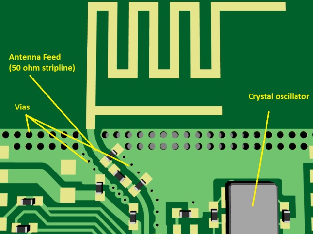
EFR32 Series 1 24GHz Matching Guide and. H 2 1 Introduction Antenna design and RF layo ut are critical in a wireless system that transmits and receives electromagnetic radiation in free space. As for the design guidelines you can follow pretty much any app note out there for antenna design and RF layout just that it should be for a single ended RF output. Either patch or omni antenna should be connected to the MBN module using 50 ohm microstrip and a UFL RF connector as shown below. Antenna keep-out area Figure 2.
 Source: embedded.com
11 18 April 2016 299411 Application note COMPANY PUBLIC. Amplified HumPROTM Series PCB Layout Guide Reference Guide RG-00110 MicroSplatch Antenna Connection This RF connection is approved with all operating modes of the module. This design uses a PCB microstrip to connect the modules Antenna castellation to the MicroSplatch surface mount antenna Linx part number ANT-916-USP. Some general guidelines when routing an RF PCB are listed below. How Adding An Antenna Changes The Design Process Embedded Com.
 Source: theengineeringknowledge.com
NRF9160 does not set requirements to antenna radiation parameters but antenna efficiency is an. Microstrip Design And External Antenna The MBN52832 module is certified with an internal PCB antenna and two external antennas. The most critical aspects of radio frequency RF circuitry are addressed and it is highly recommended to follow these design guidelines to achieve best RF performance. The 24 GHz matching principles are described in the application note AN9301. Rf Pcb Layout Overview The Engineering Knowledge.
 Source: embedded.com
Antenna selection including how to take advantage of low-cost solutions from Cypress for use in Bluetooth Low Energy BLE applications. This application note also recommends two Cypress-tested PCB antennas that can be implemented at a very low cost for use with the Bluetooth Low Energy BLE solutions that are part of Cypresss PSoC and. The antenna design and layout suggestions and the RF performance results are also discussed. Place and route decoupling capacitors and RF components first. How Adding An Antenna Changes The Design Process Embedded Com.

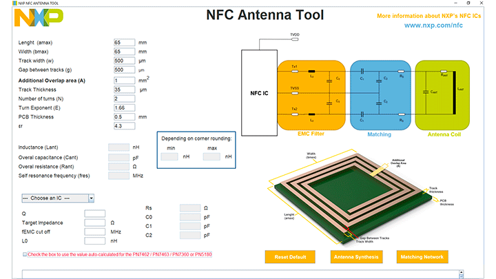
The wireless range that an end-customer gets out of an RF product with a current-limited power source such as a coin-cell battery depends greatly on the antenna design the enclosure and a good PCB layout. Combining RF analog circuitry with other low frequency analog and digital board components. The 24 GHz matching principles are described in the application note AN9301. NRF9160 does not set requirements to antenna radiation parameters but antenna efficiency is an. Nfc Antenna Design Tool Antenna Design Hub Nxp Semiconductors.

PN7120 Antenna Design and Matching Guide. The most critical aspects of radio frequency RF circuitry are addressed and it is highly recommended to follow these design guidelines to achieve best RF performance. RF Connectors PCB design guidelines for RF connectors. Layout of antenna interface example 23 Antenna radiation parameters Antenna efficiency is a measure of radiated power relative to total antenna power including losses. Bst 0001 Ble Stamp Cover Letter Antenna Design And Rf Layout Guidelines E G O Elektro Geraetebau Gmbh.
 Source: autodesk.com
For the most optimal layout make sure there arent any signal layers between your bias and ground return layers. By designing a custom antenna and PCB layout for an RF chip I think you are now supposed to have your device tested and certified by the FCC before you can actually sell it. Layout Floorplan Suggests the best positioning of circuit blocks antenna etc. This application note provides guidelines and suggestions for RF printed-circuit board PCB design and layout including some discussion of mixed-signal applications. Antenna Design Rf Layout Everyday App Note Eagle Blog.
 Source: raypcb.com
The wireless range that an end-customer gets out of an RF product with a current-limited power source. AN91445 explains antenna design in simple terms and provides guidelines for RF component selection matching network design and layout design. Note that these guidelines and example layout figures are based on the RFX300-31 RF subsystem daughter card supporting WCDMAEDGE 3G terminals. A 7 dBi omni antenna and a 6 dBi patch antenna. Antenna Design And Rf Layout Rules Part I Printed Circuit Board Manufacturing Pcb Assembly Rayming.

Layout Floorplan Suggests the best positioning of circuit blocks antenna etc. Image source Download These Guidelines Now. The antenna trace width is 20 mils throughout. Place and route decoupling capacitors and RF components first. Bst 0001 Ble Stamp Cover Letter Antenna Design And Rf Layout Guidelines E G O Elektro Geraetebau Gmbh.
 Source: pinterest.com
Once youve designed your antenna its time to figure out where it should be placed on the PCB. Place and route decoupling capacitors and RF components first. RF layout including impedance matching RF transmission lines and ground plane considerations. EFR32 Series 1 Layout Design Guide. High Frequency Hf Or Radio Frequency Rf Circuit Printed Circuit Board Pcb Design Printed Circuit Board Pcb Design Printed Circuit.
 Source: pinterest.com
NRF9160 does not set requirements to antenna radiation parameters but antenna efficiency is an. The wireless range that an end-customer gets out of an RF product with a current-limited power source. This design uses a PCB microstrip to connect the modules Antenna castellation to the MicroSplatch surface mount antenna Linx part number ANT-916-USP. MIFA Layout Top Layer Antenna Layer 50. Part 1 Designing A Wifi Pcb Trace Antenna For Esp8266 Or Esp32 Antenna Wifi Design Basics.
 Source: pinterest.com
For Bluetooth this is 31 mm but longer is always better for example Johansons layout guidelines specify 40mm ground plane length for their 24 GHz WLAN antennas. The material provides best practices guidance and should be used in conjunction with all other design and manufacturing guidelines that may apply to particular components PCB manufacturers and. This is why usually hobbyists and small companies will. Amplified HumPROTM Series PCB Layout Guide Reference Guide RG-00110 MicroSplatch Antenna Connection This RF connection is approved with all operating modes of the module. The Dropout S Guide To Pcb Trace Antenna Design Antenna Dropout Overlays.
 Source: raypcb.com
RF traces must be short and straightforward. Antenna matching circuit 2. The wireless range that an end-customer gets out of an RF product with a current-limited power source. Combining RF analog circuitry with other low frequency analog and digital board components. Antenna Design And Rf Layout Rules Part I Printed Circuit Board Manufacturing Pcb Assembly Rayming.
 Source: raypcb.com
Make the transmission lines short and straightforward in order to avoid reflections save power and reduce highfrequency issues. Antenna selection including how to take advantage of low-cost solutions from Cypress for use in Bluetooth Low Energy BLE applications. PN7120 Antenna Design and Matching Guide. Make the transmission lines short and straightforward in order to avoid reflections save power and reduce highfrequency issues. Antenna Design And Rf Layout Rules Part I Printed Circuit Board Manufacturing Pcb Assembly Rayming.

Antenna matching circuit 2. RF traces must be short and straightforward. The antenna trace width is 20 mils throughout. Image source Download These Guidelines Now. Cc2640 Pcb Antenna Design Verification An043 Bluetooth Forum Bluetooth Ti E2e Support Forums.

This application note offers a ton of other practical RF PCB design guidelines that can help to make your RF project a success. RF layout including impedance matching RF transmission lines and ground plane considerations. AN91445 explains antenna design in simple terms and provides guidelines for RF component selection matching network design and layout design. The purpose of this application note is to help users design PCBs for the EFR32 Wireless Gecko Portfolio using design practices that allow for good RF performance. Bst 0001 Ble Stamp Cover Letter Antenna Design And Rf Layout Guidelines E G O Elektro Geraetebau Gmbh.


